The design integrates the advantages of well-known domestic and international hydraulic cylinder technologies, enabling the product’s performance and quality to reach an internationally advanced level.
The main characteristics are as follows:
-
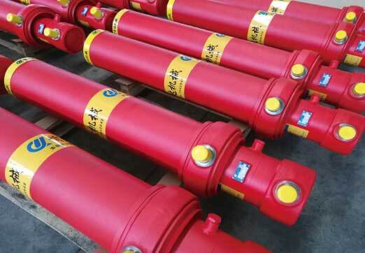
Manufactured from precision high-performance steel tubing, providing higher strength and higher system pressure resistance.
-
An optimized cylinder diameter series increases lifting capacity and improves operating efficiency.
-
Separated limit and guide structures further enhance operational stability and reliability.
-
Flexible guiding technology extends the service life of the cylinder barrel and prevents barrel scratching caused by eccentric loads and impact.
-
A complete supply system ensures higher safety, more reasonable configuration, and more timely service support.
-
The slow-descent function allows the lowering speed of the dump body to be adjusted according to operating conditions, preventing excessive impact.
Hydraulic Cylinder Technical Specifications
| Model | Height H (mm) | Working Pressure (bar) | Oil Volume (L) | Weight (kg) | Lifting Capacity (tons) | Oil Tank Type | Oil Tank Size (mm) |
|---|---|---|---|---|---|---|---|
| 150-3-4230 | 1785 | 220 | 62 | 308 | 64–81 | 77L / 60L | 570 × 300 × 520 |
| 172-4-4310 | 1450 | 220 | 74 | 317 | 66–106 | 98L / 77L | 700 × 300 × 520 |
| 172-4-4630 | 1530 | 220 | 80 | 332 | 64–101 | 112L / 88L | 750 × 300 × 520 |
| 172-4-5110 | 1650 | 220 | 88 | 355 | 62–96 | 112L / 88L | 750 × 300 × 520 |
| 172-4-5390 | 1720 | 220 | 93 | 368 | 61–98 | 132L / 108L | 750 × 300 × 600 |
| 172-4-5630 | 1780 | 220 | 97 | 379 | 61–100 | 132L / 108L | 750 × 300 × 600 |
| 196-4-5580 | 1783 | 220 | 126 | 400 | 84–105 | 153L / 130L | 750 × 350 × 600 |
| 196-4-5820 | 1843 | 220 | 131 | 412 | 83–106 | 165L / 140L | 750 × 350 × 700 |
| 196-4-6100 | 1913 | 220 | 137 | 427 | 82–106 | 165L / 140L | 750 × 350 × 700 |
| 196-5-6350 | 1653 | 220 | 128 | 408 | 60–98 | 153L / 130L | 750 × 350 × 600 |
| 196-5-6500 | 1723 | 220 | 133 | 425 | 60–98 | 165L / 140L | 750 × 350 × 700 |
| 196-5-7300 | 1843 | 220 | 147 | 453 | 59–80 | 195L / 166L | 850 × 350 × 700 |
Hydraulic System Parts List
| Position No. | Component Name | Qty |
|---|---|---|
| 1 | Imported lightweight hydraulic cylinder | 1 |
| 2 | Base support | 2 |
| 3 | Lifting bracket (left) | 1 |
| 4 | Lifting bracket (right) | 1 |
| 5 | Gear pump | 1 |
| 6 | 1″ combined sealing washer | 1 |
| 7 | 1″ straight connector | 1 |
| 8 | 1″ right-angle connector | 1 |
| 9A | Straight pipe connector | 1 |
| 9B | Straight pipe connector | 1 |
| 10 | Pump coupling | 1 |
| 11 | Oil tank | 1 |
| 12 | Air filter | 1 |
| 13 | 1-1/2″ straight pipe connector | 1 |
| 14 | 1-1/2″ ball valve | 1 |
| 15 | 1-1/2″ elbow connector | 1 |
| 16 | Lifting valve installation kit | 1 |
| 17 | Lifting valve | 1 |
| 18 | 1″ right-angle connector | 1 |
| 19 | 1″ combined sealing washer | 1 |
| 20 | 1″ straight connector | 1 |
| 21 | 1″ right-angle connector | 1 |
| 22 | Pneumatic control valve | 1 |
| 23 | Pneumatic valve installation kit | 1 |
| 24 | Three-way pipeline connector | 1 |
| 25 | Limit valve | 1 |
| 26 | High-pressure hose | 1 |
| 27 | High-pressure oil pipe | 1 |
| 28 | Low-pressure oil pipe | 1 |
| 29 | Pipe clamp | 1 |
| 30 | Pipe clip | 1 |
| 31 | High-pressure pipe clamp (optional) | 1 |
| 32 | 1″ combined sealing washer | 1 |
| 33 | 1″ straight connector | 1 |
| 34 | Body locking device (optional) | 1 |
| 35 | Cylinder anti-collision block (optional) | 1 |
| 36 | Oil tank vibration-damping block | 1 |
| 37 | Oil tank high-pressure flange | 1 |
| 38 | Air filter gasket | 1 |
| 39 | Bolt GB5783-86 M5×25 | 1 |
| 40 | Flat washer Φ5 | 1 |
| 41 | Spring washer GB93-87 Φ5 | 1 |